All posts by Nick Kaplinsky

I am an associate professor of Biology at Swarthmore College.

From the lab to the kitchen and back again

Our work on plant temperature responses requires accurate temperature control. We had been using non circulating water baths. The temperatures of these baths fluctuate by several degrees from their set point and, because the water in them is not actively mixed, the temperature also varies spatially across each bath. One solution to both of these problems is to buy circulating water baths. Circulating water baths start at a couple of thousand dollars so if you need a couple it gets expensive quickly.

Sous-vide cooking, a technique used in molecular gastronomy, involves cooking food in a vacuum sealed bag at controlled temperatures. The lore is that chefs started using laboratory recirculating water baths in their kitchens and, as the technique became more popular, cheaper circulation cookers were developed for the home market.

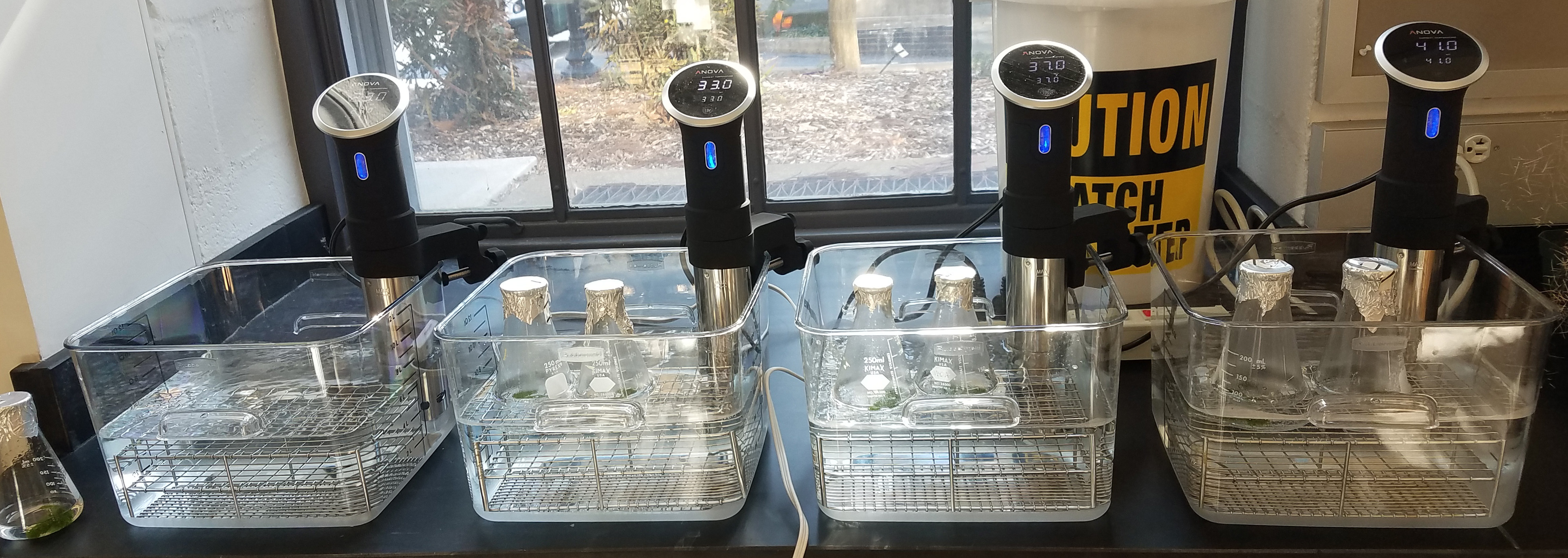
Instead of spending $10k for a set of four lab grade circulating water baths we decided to try out cheap sous vide cookers (Anova bluetooth precision sous vide cookers – $100 each at the time we bought them). This model can be calibrated using a cell phone app which connects to the cooker using Bluetooth (there is a WiFi version as well). Temperature settings can be changed in 0.5ºC increments using a dial on the front of the cooker and the app allows the calibration to be changed in  0.1ºC increments. This suggests that you should be able to get within 0.05ºC of your set temperature as long as your desired set temperature is either xx.0ºC or xx.5ºC.

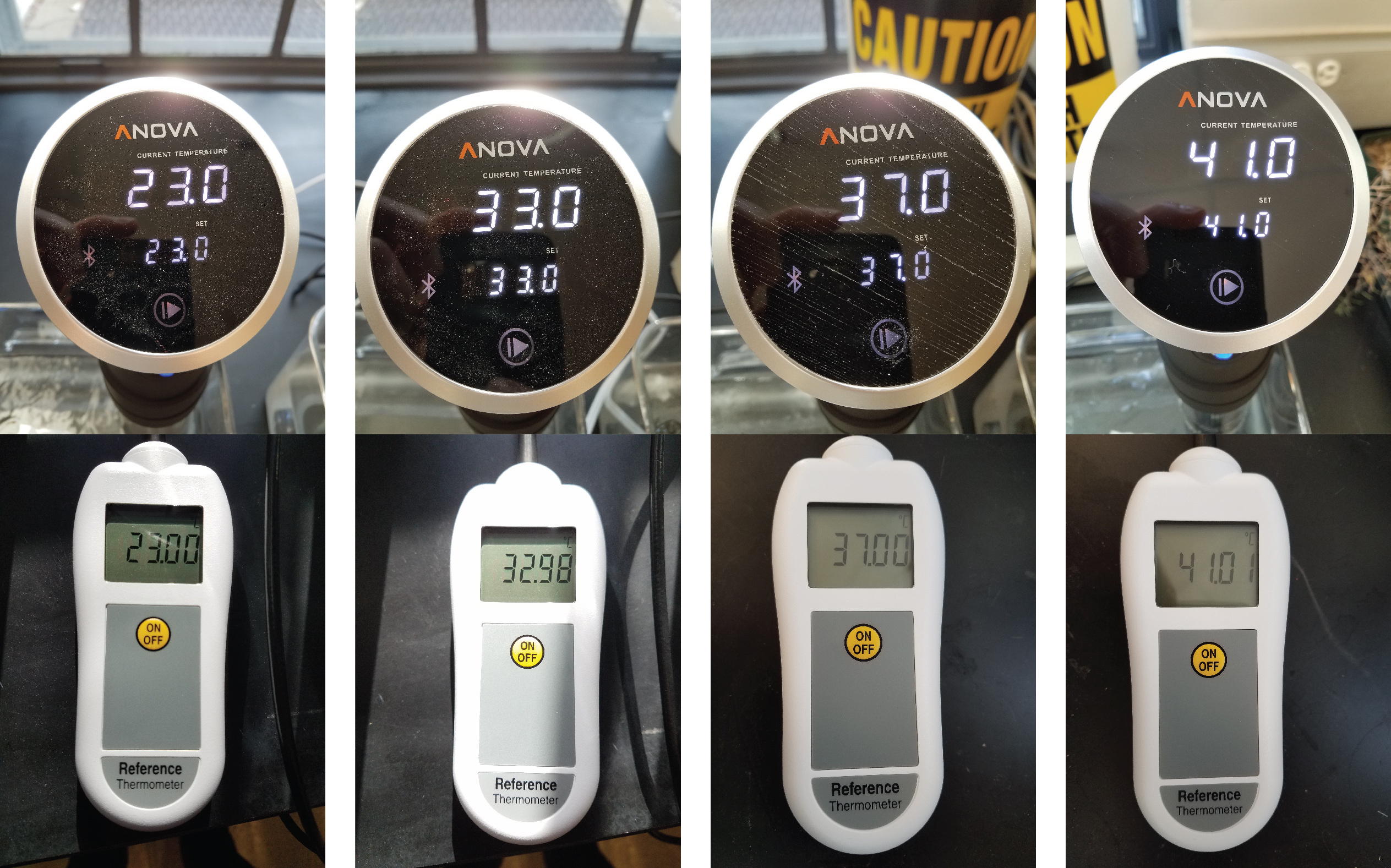
How good are these cookers? We set up our baths, let them come up to temperature, and then measure the temperature of each bath using a Thermoworks reference thermometer. Two of the four cookers required calibration. In each case the temperature was off by approximately 0.1ºC. Once calibrated, temperatures fluctuated by a couple of hundredths of a degree, were very even throughout the bath, and were stable over long periods of time (20+ hours). These baths perform much better than the ones they replaced.

I’ll update this post if we find that the performance of the cookers degrades over time. For now we’re quite happy with bringing lab inspired kitchen equipment back into the lab.


As of February 2020 the official Anova app no longer includes the ability to calibrate the cookers. This third party Android app does. It also has a simpler, faster interface than the official app and handles communications with multiple cookers much better than the official app.

Inside the ABI Solid 4 genome sequencing analyzer – A Spot Insight 4 camera and an Olympus IX81 microscope with an IX2-UCB controller (and more)

Teide Boysen’s comments about tearing apart HiSeq 2000’s and ABI Solids sent me to Ebay to see if I could find pictures of what is in the ABI machines.

It looks like there is an Olympus IX81 microscope without a stage, condensers, or  an objective head and an IX2-UCB controller. These are bundled with a Spot Insight 4 firewire camera. The camera itself is probably worth more than these listings have been selling for (~$3750). Teide also reports that the Solid sequencers also include “a complete IAI Tabletop Robot, ready for use”.

Pictures below scraped from Ebay listings for either the entire system or the microscope and camera only. Click on the thumbnails for higher resolution images.

s-l1600 (2) s-l1600 (1) s-l500 (1) s-l500 s-l1600 s-l1600 (33) s-l1600 (32) s-l1600 (31) s-l1600 (30) s-l1600 (29) s-l1600 (28) s-l1600 (27) s-l1600 (26) s-l1600 (25) s-l1600 (24) s-l1600 (23) s-l1600 (22) s-l1600 (21) s-l1600 (20) s-l1600 (19) s-l1600 (18) s-l1600 (17) s-l1600 (16) s-l1600 (15) s-l1600 (14) s-l1600 (13) s-l1600 (12) s-l1600 (11) s-l1600 (10) s-l1600 (9) s-l1600 (8) s-l1600 (7) s-l1600 (6) s-l1600 (5) s-l1600 (4) s-l1600 (3)


The ASI stages, filter wheel, and controller

The first GAIIx parts I bought on Ebay (before I knew they came from the sequencer) were the ASI stages and filter wheel. The set consists of a MS-2000 XY stage, a LS-50 linear stage (used for focus), a FW-1000 filter wheel (8 position, accepts 25mm filters), and an LX-4000 controller.

IMG_3809 IMG_3810 IMG_3812 IMG_3814 IMG_3815 IMG_3817


The stages and filter wheel are off the shelf ASI parts. The controller appears to have been custom made for Illumina. While it uses a standard ASI serial command set, each command set requires a prefix. Luckily, Erich Hoover wrote a patch for the Micro-Manager ASI device drivers (stages, filter wheel) to make the LX-4000 work.

IMG_3674

Connecting the LS-4000 is straight forward. The connection to the computer is a standard serial connection which plugs into the port labeled RS-232 on the Z/F card (not the FW-1000 card). The filter wheel connects to W0 or W1 on the FW-1000 card, the linear (Z) stage connects to the Z/F stage connector on the Z/F card, and the XY stage connects to the X/Y stage connector on the X/Y card. As far as I can tell, the linear encoder connection on the X/Y card was used to monitor whether the sliding door on the front of the GAIIx was open or closed.

If the XY stage does not work make sure to turn it on using the settings in Micro-Manager (we set this in the start up settings).

One of the filter wheels we received was slightly out of alignment. You can change the filter wheel offset using this program from ASI (runs on XP, requires installation of the bundled ActiveX control). We have not tested ASI’s newer console software with the LX-4000.


Adding dichroics (or other optics) to the GAIIx imaging core with 3D printed or machined parts

The imaging core from the GAIIx has a dichroic for the focusing laser mounted above the objective and below the tube lens and filter wheel in the infinity space of the microscope. The laser comes in from the back of the crate (hole at the back in the second image) and hits the dichroic (diagonally mounted at the bottom of the cylinder).

IMG_3803

IMG_3802

We wanted to use a high power LED as a fluorescence light source and an IR laser as a way of heating cells in the RootScope II. To do this we removed the dichroic and designed a mount which allows us to use Thorlabs filter cubes (CM1-DCH and DFM – others should work too) to replace the original dichroic without altering the rest of the optical train.

IMG_3591

The filter cubes are mounted on two 5/8″ thick plates (back plate on the left, front plate on the right in the image below). These can be machined out of 5/8″ aluminum or printed on a 3D printer.

IMG_3804

Solidworks and STL files for the plates can be found here.Back plate for mounting dichroics in Illumina core v3

The back plate bolts on top of the bracket which supports the tube lens. The front plate is connected to the back plate using 3″ long 1/2″ optical posts (TR3). The filter cubes then attach to the front plate. The CM1-DCH cubes are 0.03″ taller (to the center of the filter) than the DFM cubes so if using DFM cubes three 0.01″ shims are required. That is all there is to adding your own optics to the imaging core.

IMG_3800

Scavenging parts from the GAIIx vs the HiSeq

Imaging methods in Illumina instrumentsI’ve been wondering if there will be useful parts to be scavenged from HiSeq instruments when they reach the end of their lives. They have started showing up on Ebay but are still much too expensive to buy just for the sake of taking them apart.

This 2010 presentation (downloaded from here), in addition to schematics of the imaging compartment (p. 49-50) and an overview of the sequencing chemistry, also contains a slide which shows that the next generation of instruments are based on line scanning cameras. This means that, while there may be other useful parts in the newer sequencers, if you are building an imaging system and need a camera like the Coolsnap K4 then the GAIIx is the system to get your hands on.

Under the covers there’s a box full of lasers

In this post we’ll pull off the decorative trim and start to take a detailed look at what is in the box with a focus on the lasers.

The back of the sequencer has a power plug with two fuses and USB, serial, and camera connections.

IMG_3597 IMG_3598 IMG_3599


Removing the blue cosmetic trim panels (they simply pull off) reveals two filtered air intakes, one on each side of the instrument. There must be lots of other ways for air to get in to the sequencer as the instrument we bought had a bunch of dust bunnies in it and many of the parts inside had accumulated a fair amount of dust (evident in the pictures below).

IMG_3600 IMG_3601 IMG_3602


The panels on the sides and back are simply screwed on. Removing them reveals the guts of the machine. One side (on the left from the back) contains the imaging core, the lasers, and the main power supply. The other side (on the right from the back) contains the cooler, the pumps and actuator, and heated chamber for the fluidics, the stage controller, a USB hub and a USB to serial port converter, a 24 volt power supply, and one of only two customized circuit boards in the whole sequencer.

IMG_3608 IMG_3603 IMG_3604 IMG_3605 IMG_3607


The laser box contains the controller for the three lasers in the system (the focusing laser and the two TIRF excitation lasers). It is mounted on a shock absorbing mount which doubles as a heat sink to the side of the imaging core. Notice the dust collected on the cooling fan intake on the laser box – the filters on the sides on the GA IIx don’t appear to do a whole lot.

IMG_3613 IMG_3614 IMG_3609


The single fiber optic output of the laser box is fed into a shock mounted (the two metal plates have elastomers? between them) multimode scrambler which appears to be a re-branded General Photonics MMS-001B. It functions to generate a uniform and stable light distribution at the fiber output by literally squeezing a long strand of fiber optic at a high frequency in six directions. The output of the scrambler is used for TIRF illumination.

IMG_3612 IMG_3633 IMG_3634 IMG_3637


Removing the cover of the laser box reveals two lasers (a Laser Quantum GEM 500mW 532nm and a Melles Griot 85-RCA-400 660nm 400mW), each with a controller and a circuit board. Mounted on the circuit board is a Luminos 1×2 fiber optic switch and a Wavelength Electronics WLD3343 2.2A laser diode driver for the focus laser. The green and red lasers are connected to the 2×1 switch which controls which one is active. The output of the switch goes to the scrambler which ensures illumination uniformity.

IMG_3641 IMG_3632 IMG_3638 IMG_3639


Here are pictures of the lasers, the fiber optic switch, and the laser driver after disassembling the parts in the laser box.

IMG_3666 IMG_3645 IMG_3648 IMG_3656 IMG_3657 IMG_3664 IMG_3665


These class 3B (Melles Griot) and 4 (Quantum GEM) lasers are high power lasers. They can cause permanent vision loss in a fraction of a second. Even diffuse reflections from class 4 lasers can be eye hazards and these lasers are fire hazards! Please make sure that you familiarize yourself with laser safety (such as this excellent safety overview at Sam’s Laser FAQs) before attempting to use these lasers for any purpose other than as an integrated part of the Illumina GAIIx sequencer.

Detailed information (including pinouts, the RS232 command set, and images of both the laser and controller opened up) needed to operate the Quantum GEM 532 laser can be found here.  The RemoteApp laser control software for controlling the laser remotely can be downloaded from Laser Quantum here.

The  Melles Griot laser is apparently a custom laser but the controller is their standard universal laser controller without an enclosure. The manual for the L44000 controller contains pinout and command set information.

IMG_3646 IMG_3647


There’s an automated TIRF microscope behind the door

The GAIIx consists of a fully automated TIRF microscope, some fluidics, and temperature control hardware. Let’s start by considering the imaging core which can be seen behind the sliding door on the right side of the instrument.

IMG_3587

IMG_3582

Sliding the door up reveals the imaging core. At the bottom left is the flowcell holder with fluidics and cooling lines attached. This is mounted on an ASI MS-2000 XY stage.  Above this on the left is a Peltier device which can be lowered to heat the flowcell (more details about this hardware in a future post). In the center is the microscope. It consists of an OEM labeled Nikon CFI Plan Apo VC 20X Air 0.75 NA UV enhanced microscope objective (labeled 0500-0087. These are the specifications from Ebay auctions – I have not verified this) and the TIRF laser coming in on a fiber optic (orange) with a focusing lens mounted on an L shaped bracket. The bracket is bolted onto an ASI LS-50 linear stage which provides focus control. Next is a dicroic for the focusing laser and above that is an infinity-corrected tube lens (Thorlabs ITL2000).

Next comes an ASI FW-1000 filter wheel (8 position, accepts 25mm filters. It is labeled with red tape and the number 81 in the picture) and completing the microscope and not visible in this picture (see below) is a Photometrics Coolsnap K4 camera. To use the camera you will need the PCI card (01-490-00x) from the computer that came with the sequencer and the LVDS data cable (37-071-001 ) which connected the sequencer to the computer. These can be found separately on Ebay or bought directly from Photometrics.

The ASI stage is controlled by a LX-4000 controller which will be uncovered in a future post when I’ll start to take the sequencer apart. The ASI stages and filter wheel and the Coolsnap camera can be controlled by Micro-Manager open source microscopy software right out of the box – it is plug and play (in Windows XP).

To date we have not succeeded in getting the camera to work on a 64 bit system or reliably using Windows 7 and Micromanager using the PCI card which comes with the sequencer. Photometrics wants  $1,600 for their newer PCIe LVDS card which should allow the camera to work with their newer software on a modern 64 bit system. The ASI stage and filter wheel work with any OS as they are controlled through a serial port connection.

As a preview of what is coming next, here is a picture of a GAIIx imaging core built up into the RootScope II. Unlike the first Rootscope which was built using these parts bought separately, the Rootscope II takes advantage of the extremely rigid frame contained in the GAIIx which nicely aligns the optical train and the camera. As you can see, by buying a whole instrument you get a fully functional automated microscope out of the box. Because it contains a tube lens and infinity objective you can add any components you want if the original setup does not provide the functionality you need.

IMG_3589

In the Rootscope II we have jacked up the frame like a monster truck to make space for adding optics between the objective and the tube lens. The Nikon objective has been replaced with a turret and Mitutoyo infinity-corrected long working distance objectives. We have also removed the flowcell holder and associated fluidics as well as the focusing laser dichroic to make room for two Thorlabs dichroic cubes, one for the LED excitation source and one for a 1470nm IR laser we are using to heat small groups of cells. 3D printed  mounting plates are used to mount these parts into the GAIIx frame – I’m happy to share the design files if they might be useful.

IMG_3591

In my next post I’ll open up the box and provide a close up look at the other parts inside including the stage controller, the lasers (a Laser Quantum GEM 500mW 532nm and a Melles Griot 85-RCA-400 660nm 400mW, both fiber coupled), and the fluidics system.

Repurposing an Illumina GAIIx sequencer

GAIIx on EbayMy lab has been building custom high content microscopes using parts that turned out to come from Illumina GAIIx sequencers. In this blog I’ll be tearing down a GAIIx bought on ebay for a fraction of it’s original price ($350 to $500k, these kinds of instruments don’t come with a list price) to show you how to take it apart and how to repurpose the high quality parts it contains. The Greenleaf lab at Stanford (and possibly other labs) are also taking advantage of the cheap availability of retired GAIIx sequencers to enable innovative new experimental approaches. A teardown (but no repurposing) of an earlier version of the sequencer can be found here and here.

The GAIIx just arrived today. I’ll tear it down over the next couple of weeks and document what’s inside.

IMG_3580